Automotion Components Bearing Support Units
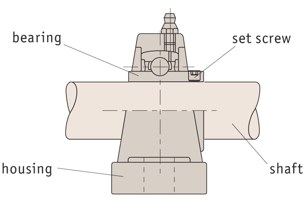
What is...
Materials
Housing material options
Cast iron housing
Standard version, passivated and painted Ø12-120mm.
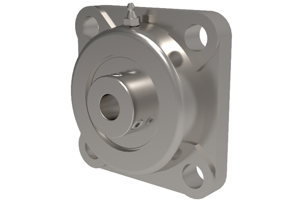
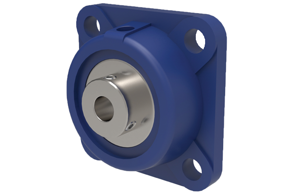
Stainless steel housing
Stainless AISI 304, Ø12-60mm.
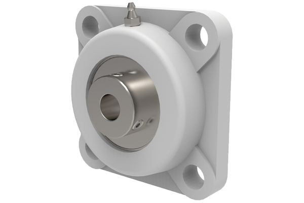
Thermoplastic housing
Food grade applications, smooth PBT resin material, Ø20-40mm.
Technical specification - materials
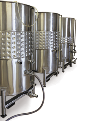
Suitable for:
- Wet environments.
- Chemical environments.
- Frequent wash downs.
e.g. food, pharmaceuticals, bottling, outdoor application etc.
Protective end caps made of stainless steel, SCC and SCO models
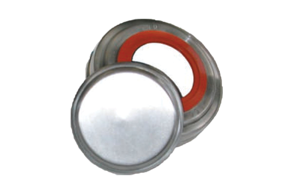
- Open protective end cap for through shafts with double-lip seal made of flourine elastomer.
- Closed protective end cap for shaft ends.
- Stainless steel AISI 304.
- Shafts Ø 12 - 60mm.
- Standard sizes available from stock.
- Stainless steel self-aligning units. Stainless steel (AISI 304 body) with AISI 440C stainless bearing unit.
- For shafts Ø 12-60mm.
- Lubricated with food grade grease (USDA H1 approved), Mobil FM102.
- Temperature range -20°C to +120°C.
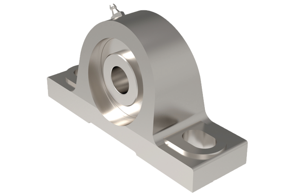
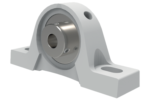
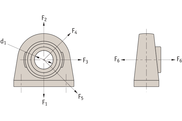
Pillow block
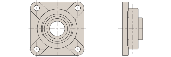
Four point flange
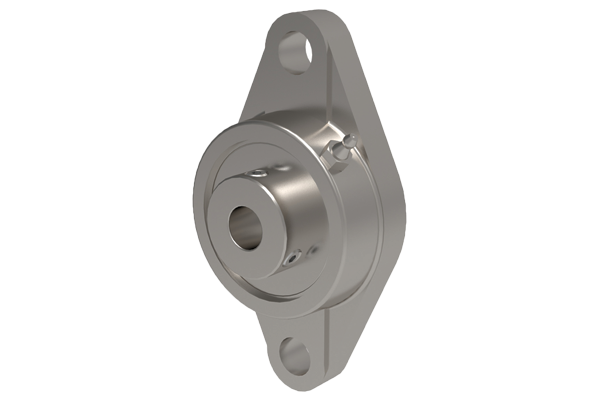
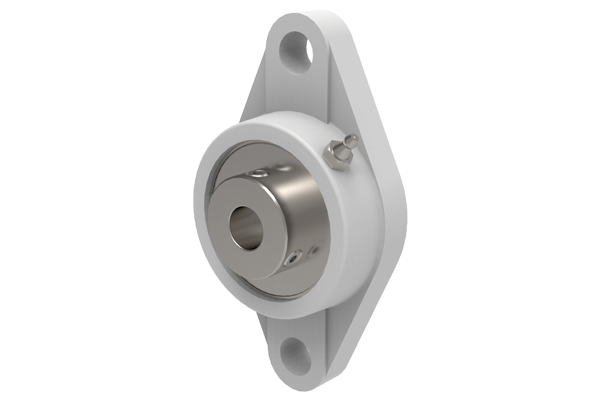
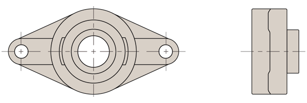
Two point flange
- Generally used in food, pharmaceutical and chemical industries, or where washdown is needed/outdoor applications.
- Use with h6 tolerance shafts.
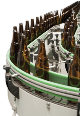
Ball bearing units made of stainless steel are used in areas where corrosion resistance is a must. In these areas where high atmospheric humidity or the requirement for periodic washdown of the equipment is necessary to prevent bacteria growth, conventional ball bearing units made of cast iron do not suit.
We off er a comprehensive standard range of ball bearing units made of stainless steel. To satisfy the requirements of the pharmaceutical and food industries all our ball bearing units made of stainless steel are filled with grease meeting the USDA H1 food grade specification.
Thermoplastic
- Thermoplastic self-aligning unit, with stainless steel insert.
- For diameters of shaft 20-40mm.
- White PBT resin (prevents retention of dust, mould and bacteria).
- Lubricated with food grade grease (USDA H1 approved).
- Temperature range -15°C to +90°C.
- Excellent chemical resistance (acids, bases, organic solvents, salts etc.).
Pillow block
Four point flange
Two point flange
- Can be used in wet or chemical environments such as bottling lines, food or pharmaceutical production lines, outdoor applications etc.
- Use with h6 tolerance shafts.
General Guidance
Pillow Bearings
Use with Automotion linear shafts L1770-L1774
Options
Pillow block
Four point flange
Two point flange
Stainless Steel
| Bearing i/d Ø | Max. rpm | Max. dynamic bearing load kN | Max. static bearing load kN |
| 12 | 4800 | 10,1 | 6,8 |
| 15 | 4800 | 10,1 | 6,8 |
| 17 | 4800 | 10,1 | 6,8 |
| 20 | 4800 | 10,1 | 6,8 |
| 25 | 4000 | 11,0 | 8,0 |
| 30 | 3400 | 15,3 | 11,5 |
| 35 | 3000 | 20,1 | 15,6 |
| 40 | 2600 | 22,8 | 18,2 |
| 45 | 2400 | 25,7 | 20,8 |
| 50 | 2200 | 27,5 | 23,7 |
| 55 | 1800 | 34,0 | 25,5 |
| 60 | 1600 | 41,0 | 31,5 |
| Ø | Set screw | Torque to Nm |
| 12-30 | M6 x 1 | 8,5 |
| 35-40 | M8 x 1 | 20 |
| 45-60 | M10 x 1,5 | 40 |
| Order no. | F1 | F2 | F3 | F4 | F5 | F6 | Ød1 |
| L1870.012-020 | 160 | 66 | 110 | 50 | 160 | 34 | 12-20 |
| L1870.012-025 | 180 | 74 | 120 | 56 | 180 | 36 | 25 |
| L1870.012-030 | 240 | 100 | 180 | 70 | 240 | 44 | 30 |
| L1870.012-035 | 320 | 120 | 200 | 88 | 320 | 48 | 35 |
| L1870.012-040 | 360 | 130 | 220 | 90 | 360 | 50 | 40 |
| L1870.012-045 | 380 | 140 | 240 | 98 | 380 | 52 | 45 |
| L1870.012-050 | 380 | 150 | 280 | 110 | 380 | 64 | 50 |
| L1870.012-055 | 475 | 191 | 350 | 262 | 475 | 80 | 55 |
| L1870.012-060 | 587 | 236 | 433 | 324 | 587 | 99 | 60 |
| Order no. | F1 | F2 | F3 | F4 | F5 | F6 | Ød1 |
| L1871.012-020 | 160 | 66 | 110 | 50 | 160 | 34 | 12-20 |
| L1871.012-025 | 180 | 74 | 120 | 56 | 180 | 36 | 25 |
| L1871.012-030 | 240 | 100 | 180 | 70 | 240 | 44 | 30 |
| L1871.012-035 | 320 | 120 | 200 | 88 | 320 | 48 | 35 |
| L1871.012-040 | 360 | 130 | 220 | 90 | 360 | 50 | 40 |
| L1871.012-045 | 380 | 140 | 240 | 98 | 380 | 52 | 45 |
| L1871.012-050 | 380 | 150 | 280 | 110 | 380 | 64 | 50 |
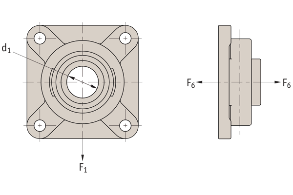
| Order no. | F1 | F2 | F3 | F4 | F5 | F6 | Ød1 |
| L1872.012-020 | 86 | - | - | - | - | 36 | 12-20 |
| L1872.012-025 | 130 | - | - | - | - | 50 | 25 |
| L1872.012-030 | 130 | - | - | - | - | 60 | 30 |
| L1872.012-035 | 130 | - | - | - | - | 70 | 35 |
| L1872.012-040 | 140 | - | - | - | - | 78 | 40 |
| L1872.012-045 | 200 | - | - | - | - | 90 | 45 |
| L1872.012-050 | 200 | - | - | - | - | 100 | 50 |
| L1872.012-055 | 255 | - | - | - | - | 125 | 55 |
| L1872.012-060 | 315 | - | - | - | - | 155 | 60 |
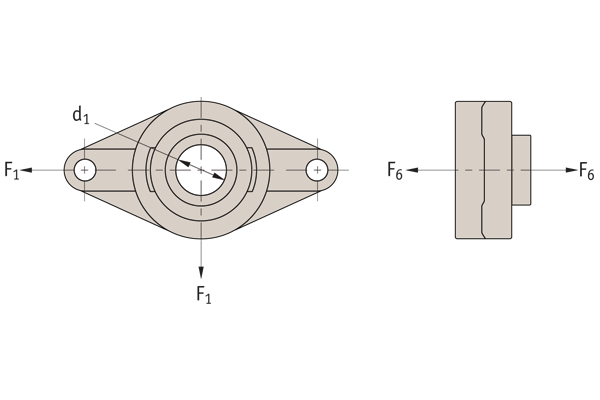
| Order no. | F1 | F2 | F3 | F4 | F5 | F6 | Ød1 |
| L1873.012-020 | 48 | - | - | - | - | 24 | 12-20 |
| L1873.012-025 | 76 | - | - | - | - | 32 | 25 |
| L1873.012-030 | 76 | - | - | - | - | 40 | 30 |
| L1873.012-035 | 80 | - | - | - | - | 46 | 35 |
| L1873.012-040 | 82 | - | - | - | - | 54 | 40 |
| L1873.012-045 | 120 | - | - | - | - | 64 | 45 |
| L1873.012-050 | 124 | - | - | - | - | 78 | 50 |
Installation
Description of the installation steps
Self-aligning bearing units must be installed under conditions that ensure maximum bearing life. We recommend that you refer to the following chapters and follow the reference procedures for this type of bearing unit.
When installing sealed bearings, grease the seals to avoid dry operation when the shaft first starts to rotate.
Make sure that the seating surfaces are perfectly clean and flat before starting any installation operations.
Install the shaft by mounting the bearing unit housings on the supporting frame. Tighten the inner ring retaining screw to the required torque indicated in the torque value table.
In all cases the shaft is installed first by attaching the bearing unit housings to the supporting frame. Tighten the screws in alternate diagonals.
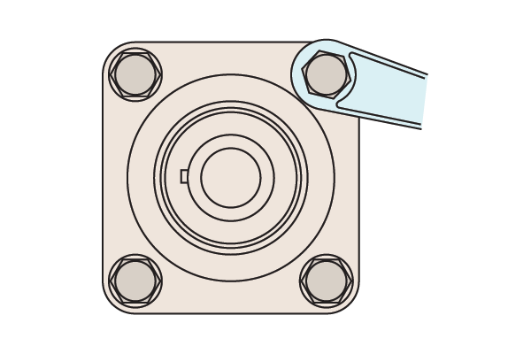
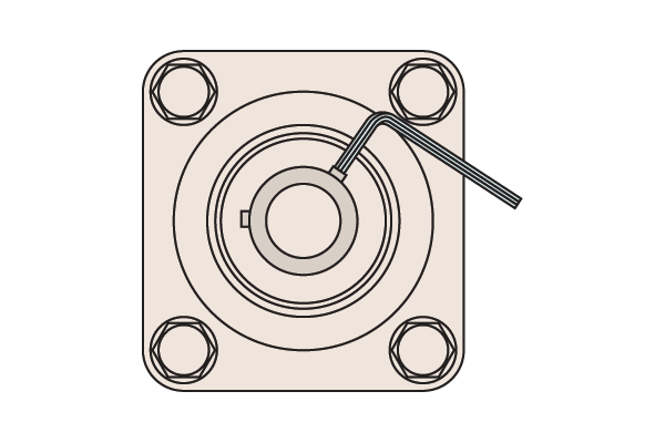
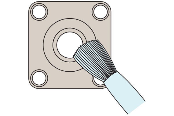
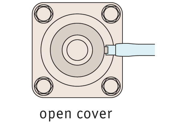
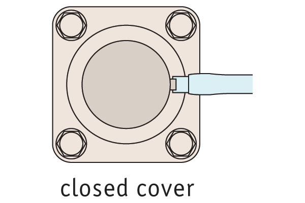
Installation / removal of protective covers
The covers (if required) are installed by snap-fitting, which can be done with a light blow of a mallet. They are removed by inserting the tip of a screwdriver into the cavity and applying light pressure to release them.
Installation
- Check clean and flat surface
- Tighten retaining screws, diagonal method
- Check shaft can be rotated by hand
- Check no distortion
Tightening of stainless steel fitting screws
M6 thread, torque to 3.9 Nm
M8 thread, torque to 8.3 Nm
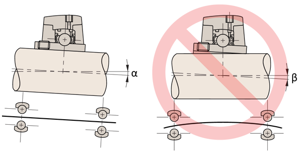
Permissible misalignment
- With provision for re-lubrication, the bearing can swivel inside the housing up to an angle α of about 5° (the groove is aligned with the lubricator hole) and 8° without provision for re-lubrication
- Pay attention to the swivelling of the bearing in the bearing unit. Permanent swivelling induced by rotational deflection of the shaft would cause wear of the housing and is therefore not allowable (angle ß)
- The maximum allowable values are those for deep-groove ball bearings corresponding to the same shaft diameter (maximum angle ß < 0.5 )
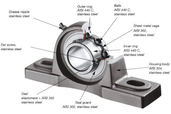
Technical Specs
For cast iron housings
- Single row radial contact self-aligning bearings (steel 100Cr6).
- Re-lubricatable.
- Fixing to shaft via set screw.
- Operating temperature range -20° to +100°
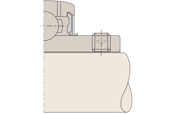
Shaft fixing set screw
2 set screws at 120° with hexagon socket and knurled cup point, recommended shaft tolerance h6/h7.
| Set screw | Max. tightening torque (Nm) | Hexagon socket A/F |
| M5 x 0,8 | 3,5 | 2,5 |
| M6 x 1 | 5,5 | 3,0 |
| M8 x 1 | 11,5 | 4,0 |
| M10 x 1,25 | 22,0 | 5,0 |
| M12 x 1,25 | 33,0 | 6,0 |
| M14 x 1,5 | 42,0 | 7,0 |
| M16 x 1,5 | 64,0 | 8,0 |
| M18 x 1,5 | 75,0 | 9,0 |
| M20 x 1,5 | 120,0 | 10,0 |
For stainless & thermoplastic housings
- Single row radial contact self-aligning bearings (stainless steel AISI 440C), stainless steel cage.
- Lubricated with food grade grease.
- Fixing to shaft via set screw.
Lubrication
Our units are lubricated for life. If re-lubrication is necessary (because of severe operating conditions), use a lithium soap base with a viscosity of 100mm2/s at 40°C.
Installation
Shaft misalignment is compensated to a certain degree by the shaft-aligning bearings.
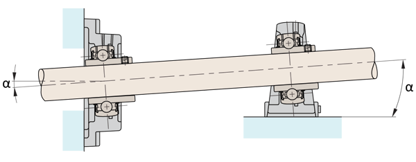
If re-lubrication required
α = ± 2°
If no re-lubrication
α = ± 5°
When using protective end caps
α = ± 5°
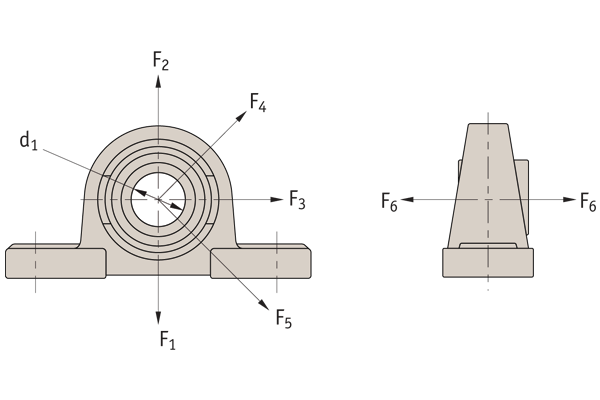
The radial loads of the cast iron bearing supports are limited by the bearings themselves – the housings can withstand the maximum loads. Please see the part numbers for dynamic and static radial loads. The maximum axial loads are 50% of the maximum static radial loads. The standard bearing have a C3 clearance.
| Bore nominal size (mm) | Bore nominal size (mm) | Radial bearing clearance (μ) C3 | Radial bearing clearance (μ) C3 |
| Above | Up to | Min. | Max. |
| 10 | 18 | 11 | 25 |
| 18 | 24 | 13 | 28 |
| 24 | 30 | 13 | 28 |
| 30 | 40 | 15 | 33 |
| 40 | 50 | 18 | 36 |
| 50 | 65 | 23 | 43 |
| 65 | 80 | 25 | 51 |
| 80 | 100 | 30 | 58 |
| 100 | 120 | 36 | 66 |
| 120 | 140 | 41 | 81 |
When choosing a suitable bearing size – this depends on the load and speed required. If the load acts mainly whilst the bearing rotates then it is dynamic load, if it acts mainly during
no movement or low speeds then it is a static load. The maximum for both of these for each bearing is shown in the part tables.
Dynamic equivalent loads:
For some situations the bearing will have to withstand both radial and axial loads and we then need to calculate an equivalent dynamic load using the following equation:

P = Dynamic equivalent load (kN)
Fr = Actual radial load (kN)
Fa = Actual axial load (kN)
X = Radial factor
Y = Axial factor
Load ratio table 1:
| Fa C0r | e | Fa ≤ e FrX | Fa ≤ e FrY | Fa > e FrX | Fa > e FrY |
| 0,014 | 0,19 | 1 | 0 | 0,56 | 2,30 |
| 0,028 | 0,22 | 1 | 0 | 0,56 | 1,99 |
| 0,056 | 0,26 | 1 | 0 | 0,56 | 1,71 |
| 0,084 | 0,28 | 1 | 0 | 0,56 | 1,55 |
| 0,110 | 0,30 | 1 | 0 | 0,56 | 1,45 |
| 0,170 | 0,34 | 1 | 0 | 0,56 | 1,31 |
| 0,280 | 0,38 | 1 | 0 | 0,56 | 1,15 |
| 0,420 | 0,42 | 1 | 0 | 0,56 | 1,04 |
| 0,560 | 0,44 | 1 | 0 | 0,56 | 1,00 |
e = Limiting value
C0r = Radial static load rating (see dimension tables for ball bearing units)
Static equivalent loads
For situations where there are radial and axial loads on the static or slow moving bearings:
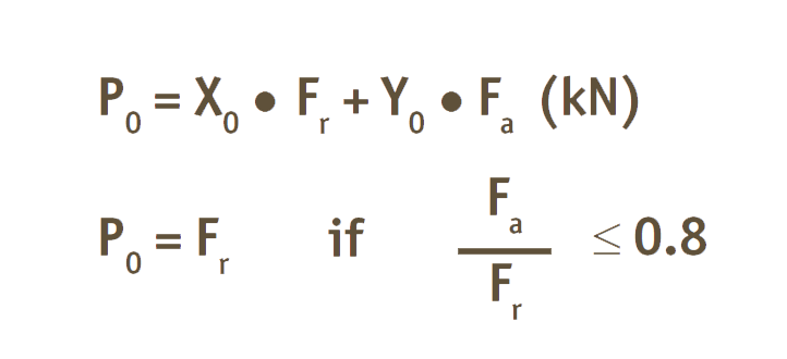
P0 = Static equivalent load (kN)
X0 = Static radial factor
Y0 = Static axial factor
For all bearing inserts the following applies:
X0 = 0.6
Y0 = 0.5
Using the ratio fs it can be checked if suficient static dimensioning for the insert has been ensured:
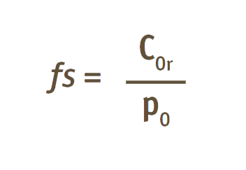
Some standard values are:
fs = 0.7 Minimal demands for running smoothness and rotating movement
fs = 1.0 occasional rotating bearing, normal demands for running
fs = 2.0 smoothness, high demands for running smoothness
It should be noted that this ratio does not provide any assurance against a break or similar, but instead it is assurance against excessive local deformation in the rolling contact (ball/raceway).
Calculating bearing life
When calculating bearing life for bearing units, the following applies:

If the bearing life should be specified in hours, the following applies:
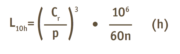
n = speed (min-1)
Bearing life calculation
The bearing life of a UCP210 ball bearing unit under the following conditions:
Radial load:
Axial load:
Normal operating condition speed:
UCP210 ball bearing unit data:
Fr = 2 kN
Fa = 1.7 kN
n = 1800 min-1
Cr = 35.1 kN
C0r = 23.2 kN
Dynamic equivalent bearing load:
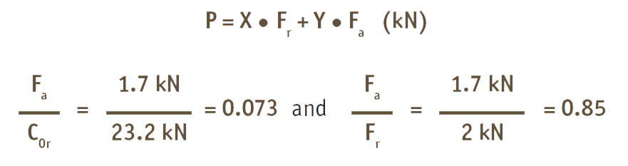
From load ratio table 1:
with Fa/C0r = 0.073, e is determined to be ≈ 0.28
with Fa/Fr = 0.85 > e = 0.28
X = 0.56
Y = 1.55
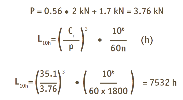
The theoretical bearing life of the bearing unit, under normal operating conditions, is 7532 hours.
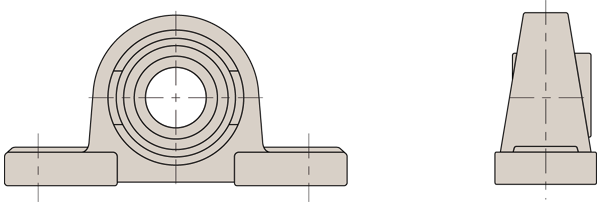
L1860 Pillow block housing
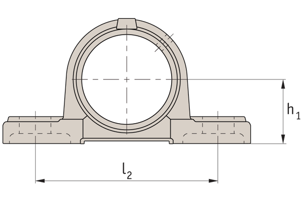
| For shaft i/d d1 | h1 ± | l2 ± |
| 12-20 | ±0,15 | ±0,70 |
| 25 | ±0,15 | ±0,70 |
| 30 | ±0,15 | ±0,70 |
| 35 | ±0,15 | ±0,70 |
| 40 | ±0,15 | ±0,70 |
| 45 | ±0,15 | ±0,70 |
| 50 | ±0,15 | ±0,70 |
| 55 | ±0,20 | ±1,00 |
| 60 | ±0,20 | ±1,00 |
| 65 | ±0,20 | ±1,00 |
| 70 | ±0,20 | ±1,00 |
| 75 | ±0,20 | ±1,00 |
| 80 | ±0,20 | ±1,00 |
| 90 | ±0,30 | ±1,00 |
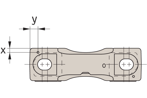
| x | y | Dowel Ø |
| 10,0 | 59,0 | 3 |
| 12,0 | 59,0 | 3 |
| 13,0 | 72,0 | 3 |
| 14,5 | 73,0 | 4 |
| 16,0 | 81,5 | 4 |
| 16,0 | 88,0 | 5 |
| 18,0 | 91,0 | 5 |
| 20,0 | 101,0 | 6 |
| 20,0 | 110,0 | 6 |
| - | - | - |
| 21,5 | 119,0 | 6 |
| 22,0 | 121,5 | 6 |
| 26,0 | 132,0 | 8 |
| 28,5 | 151,0 | 10 |
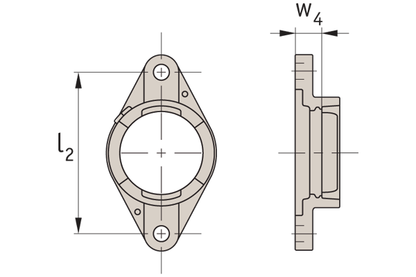
L1862 Square flanged bearing housing
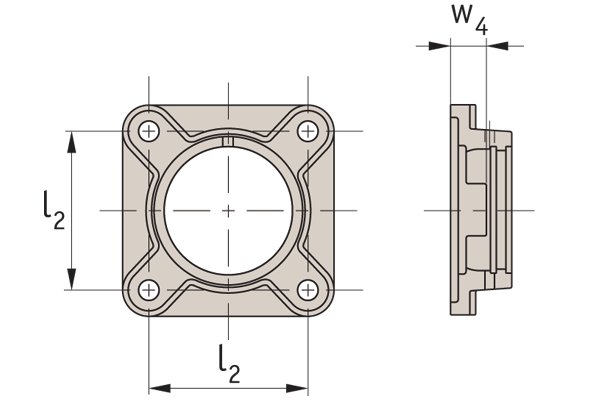
| For shaft i/d d1 | l2 ± | w4 ± | Radial runout |
| 12-20 | ±0,70 | ±0,50 | 0,20 |
| 25 | ±0,70 | ±0,50 | 0,20 |
| 30 | ±0,70 | ±0,50 | 0,20 |
| 35 | ±0,70 | ±0,50 | 0,20 |
| 40 | ±0,70 | ±0,50 | 0,20 |
| 45 | ±0,70 | ±0,50 | 0,20 |
| 50 | ±0,70 | ±0,50 | 0,20 |
| 55 | ±1,00 | ±0,80 | 0,30 |
| 60 | ±1,00 | ±0,80 | 0,30 |
| 65 | ±1,00 | ±0,80 | 0,30 |
| 70 | ±1,00 | ±0,80 | 0,30 |
| 75 | ±1,00 | ±0,80 | 0,30 |
| 80 | ±1,00 | ±0,80 | 0,30 |
| 90 | ±1,00 | ±0,80 | 0,30 |
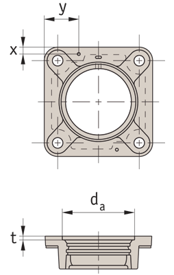
| x | y | Dowel Ø | da | t |
| 36,0 | 13,0 | 3 | 50,80 | 3,2 |
| 40,5 | 15,0 | 3 | 63,50 | 3,2 |
| 46,0 | 17,0 | 3 | 76,20 | 4,0 |
| 51,0 | 18,0 | 4 | 88,90 | 4,0 |
| 57,0 | 20,0 | 4 | 88,90 | 4,0 |
| 60,5 | 21,0 | 5 | 98,42 | 4,0 |
| 63,5 | 22,0 | 5 | 101,60 | 4,0 |
| 71,0 | 25,0 | 6 | 107,95 | 4,0 |
| 77,5 | 27,0 | 6 | 125,40 | 4,0 |
| 85,0 | 29,0 | 6 | 161,92 | 4,0 |
| 85,0 | 29,0 | 6 | 161,92 | 4,0 |
| 88,5 | 30,0 | 6 | 161,92 | 4,0 |
| 88,5 | 30,0 | 6 | 161,92 | 4,0 |
| 103,5 | 36,0 | 6 | 179,37 | 4,0 |
L1864 Oval flanged bearing housing
| For shaft i/d d1 | l2 ± | w4 ± | Radial runout |
| 12-20 | ±0,70 | ±0,50 | 0,20 |
| 25 | ±0,70 | ±0,50 | 0,20 |
| 30 | ±0,70 | ±0,50 | 0,20 |
| 35 | ±0,70 | ±0,50 | 0,20 |
| 40 | ±0,70 | ±0,50 | 0,20 |
| 45 | ±0,70 | ±0,50 | 0,20 |
| 50 | ±0,70 | ±0,50 | 0,20 |
| 55 | ±1,00 | ±0,80 | 0,30 |
| 60 | ±1,00 | ±0,80 | 0,30 |
| 65 | ±1,00 | ±0,80 | 0,30 |
| 70 | ±1,00 | ±0,80 | 0,30 |
| 75 | ±1,00 | ±0,80 | 0,30 |
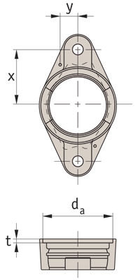
| x | y | Dowel Ø | da | t |
| 31,0 | 14,5 | 3 | 50,80 | 3,2 |
| 35,0 | 16,0 | 3 | 63,50 | 3,2 |
| 42,5 | 17,0 | 3 | 73,00 | 4,0 |
| 50,0 | 17,0 | 4 | 82,50 | 4,0 |
| 55,0 | 19,0 | 4 | 88,90 | 4,0 |
| 58,0 | 21,0 | 5 | 98,42 | 4,0 |
| 60,0 | 22,5 | 5 | 101,60 | 4,0 |
| 70,0 | 26,0 | 6 | 107,95 | 4,0 |
| 75,0 | 26,0 | 6 | 125,40 | 4,0 |
| 85,0 | 28,0 | 6 | 142,00 | 4,0 |
| 85,0 | 28,0 | 6 | 142,00 | 4,0 |
| 85,0 | 30,0 | 6 | 142,00 | 4,0 |
L1869 Take up unit housing
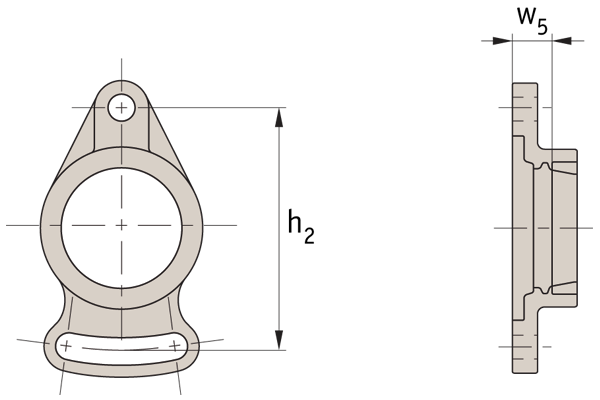
| For shaft i/d | h2± | w5± |
| 12-20 | ±0,70 | ±0,50 |
| 25 | ±0,70 | ±0,50 |
| 30 | ±0,70 | ±0,50 |
| 35 | ±0,70 | ±0,50 |
| 40 | ±0,70 | ±0,50 |
| 45 | ±0,70 | ±0,50 |
| 50 | ±0,70 | ±0,50 |
| 55 | ±1,00 | ±0,80 |
| 60 | ±1,00 | ±0,80 |
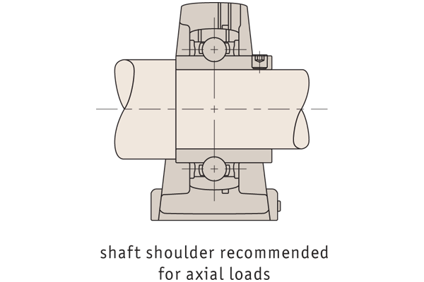
Axial load capacity
The axial load capacity of the inserts depends largely on the type of fixing on the shaft. The inner design of the raceways and balls is of little importance in most cases. A further factor is the shaft tolerance used.
In order to attain the largest possible axial load capacity for the respective type of fixing, it is necessary that the fixing element (e.g. set screw, adapter sleeve) is secured at the specified tightening torque.
For applications with strong vibrations or shock loads it is recommended to set the inner ring against a shaft shoulder and to secure with a groove nut and lock washer as necessary. In this case, the axial load carrying capacity of the inserts can be fully utilised. The axial load rating can be up to 0.5 times the radial static load rating C0r.
Bearing tolerances
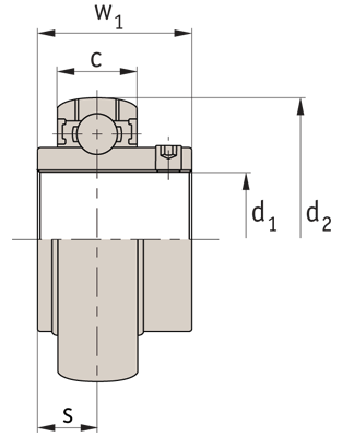
| For shaft i/d | w1 | d2 μ |
| 12-20 | ±0,020 | +0,0 -11 |
| 25 | ±0,020 | +0,0 -11 |
| 30 | ±0,020 | +0,0 -11 |
| 35 | ±0,020 | +0,0 -11 |
| 40 | ±0,020 | +0,0 -11 |
| 45 | ±0,020 | +0,0 -11 |
| 50 | ±0,025 | +0,0 -11 |
| 55 | ±0,025 | +0,0 -11 |
| 60 | ±0,025 | +0,0 -11 |
| 65 | ±0,025 | +0,0 -11 |
| 70 | ±0,025 | +0,0 -11 |
| 75 | ±0,025 | +0,0 -11 |
| 80 | ±0,035 | +0,0 -15 |
| 90 | ±0,035 | +0,0 -15 |
L1865 Take up unit housing
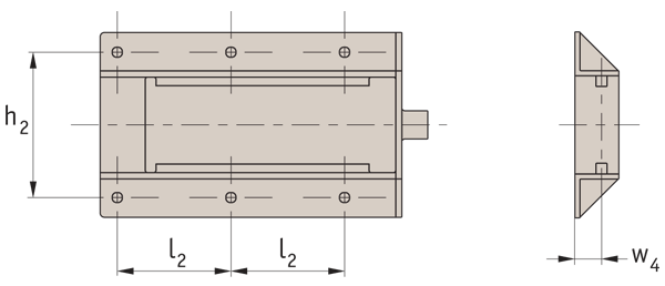
| All sizes | h2 ± | l2 ± | w4 ± |
| ±0,70 | ±0,70 | ±0,50 |
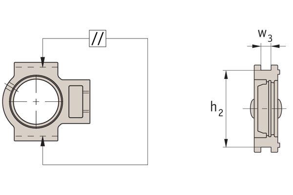
| For shaft i/d | w3 max. | w3 min. | h2 max. | h2 min. | Parallelism of guiding groove max. |
| 12-20 | +0,20 | 0,00 | 0,00 | -0,50 | 0,50 |
| 25 | +0,20 | 0,00 | 0,00 | -0,50 | 0,50 |
| 30 | +0,20 | 0,00 | 0,00 | -0,50 | 0,50 |
| 35 | +0,20 | 0,00 | 0,00 | -0,50 | 0,50 |
| 40 | +0,20 | 0,00 | 0,00 | -0,50 | 0,50 |
| 45 | +0,20 | 0,00 | 0,00 | -0,50 | 0,50 |
| 50 | +0,20 | 0,00 | 0,00 | -0,50 | 0,50 |
| 55 | +0,30 | 0,00 | 0,00 | -0,80 | 0,60 |
| 60 | +0,30 | 0,00 | 0,00 | -0,80 | 0,60 |
| 65 | +0,30 | 0,00 | 0,00 | -0,80 | 0,60 |
| 70 | +0,30 | 0,00 | 0,00 | -0,80 | 0,60 |
| 75 | +0,30 | 0,00 | 0,00 | -0,80 | 0,60 |
| 80 | +0,30 | 0,00 | 0,00 | -0,80 | 0,60 |
| 90 | +0,30 | 0,00 | 0,00 | -0,80 | 0,60 |
| Properties | Unit | |
| Tensile strength at yield | N/mm2 | 115 |
| Elongation at yield | % | 3 |
| Tensile modulus | N/mm2 | 8,000 |
| Flexural yield strength | N/mm2 | 170 |
| Flexural modulus | N/mm2 | 7,000 |
| Notched impact strength Charpy | k/m2 | 12 |
| Notched impact strength IZOD | J/m | 100 |
| Hardness H358/10 | N/mm2 | 104 |
| Hardness H358/60 | N/mm2 | 101 |
| Hardness Rockwell | - | L102 |
| Thermal | Unit | |
| Oxygen index | % | 19 |
| Flame retardancy (1/6mm thickness) | - | 94B |
| Heat resistance: Vicat, method B | °C | 210-215 |
| Thermal conductivity | W/m2C | 0,19 |
| Mould shrinkage flow | % | 0,4-0,6 |
| Cross flow direction | % | 0,6-0,8 |
| Physical | Unit | |
| Water absorption: Saturation for 24h at 23°C | % | 0,06 |
For units L1876 - L1878
All data expressed in terms of % retention of tensile strength.
| Chemical environment | °C | Immulsion days | % retention of strength |
| Acids | |||
| 10% Hydrochloric | 232323 | 3090180 | 898582 |
| 10% Sulphuric | 232323 | 3090180 | 979490 |
| 36% Sulphuric (battery) | 23236666 | 3018030180 | 97968435 |
| 10% Acetic | 2323 | 30180 | 8988 |
| Bases | |||
| 5% Potassium hydroxide | 2323 | 3090 | 8310 |
| 10% Sodium hydroxide | 2323 | 30180 | 2- |
| 10% Ammonium hydroxide | 232323 | 3090180 | 908758 |
| Salts | |||
| 10% Zinc chloride | 2525 | 3090 | 9794 |
| 10% Sodium hydroxide | 2525 | 3090 | 9898 |
| 10% Sodium chloride | 2525 | 3090 | 9797 |
| Organic solvents | |||
| Ethyl alcohol | 2323 | 30180 | 9994 |
| Methyl alcohol | 2323 | 30180 | 9176 |
| Isopropyl-alcohol | 2323 | 30180 | 100100 |
| Isopropyl-alcohol & water (50/50) | 2323 | 30180 | 9396 |
| Turpentine | 2323 | 30180 | 6692 |
| Acetone | 2323 | 30180 | 9063 |