Automotion Components Positioning Stages
What is...
Features
There are two different load ratings for these stages.
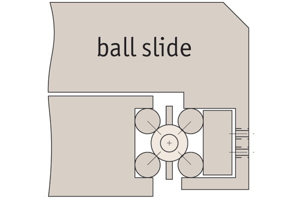
Ball slides:
These have precision steel balls rolling in the tracks.
They are the least expensive, loads up to 28Kg.
Locking options
Posi-lock:
Allows locking of the carriage in place with a friction locking mechanism.

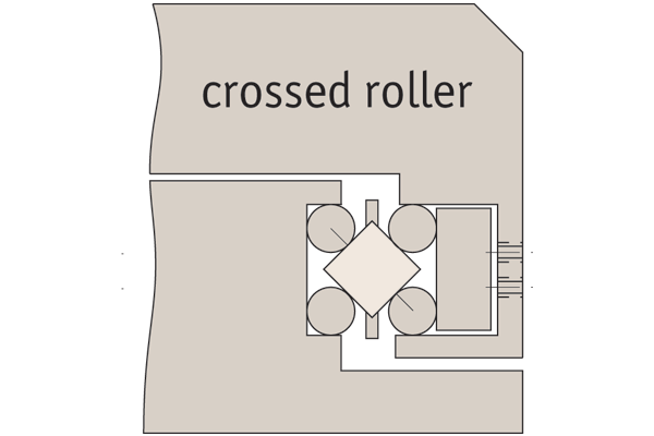
Cross roller slides:
These have the same dimensions but have rollers allowing the slide to carry large loads and absorb greater moment loads up to 54Kg.
Locking micrometer:
Locking of the micrometer to fix the micrometer setting.
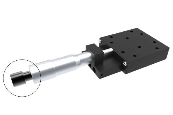
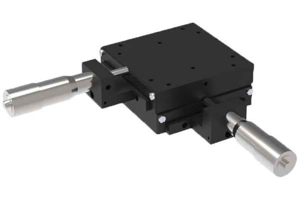
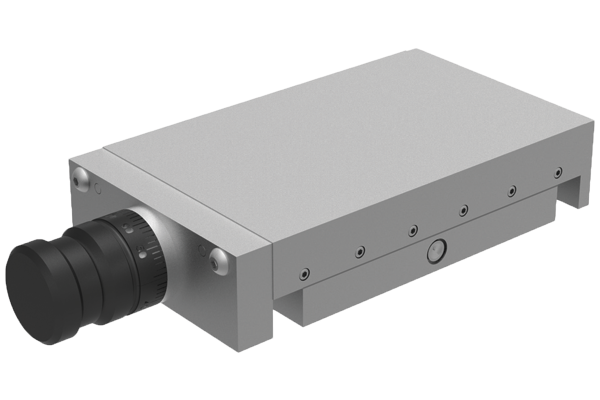
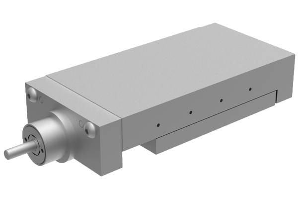
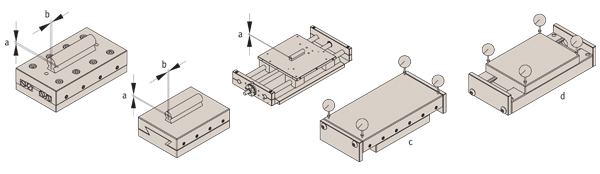
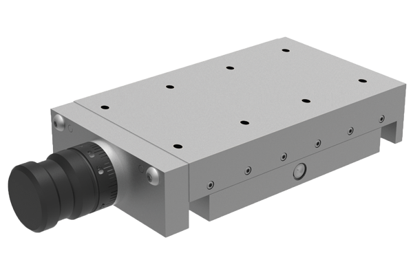
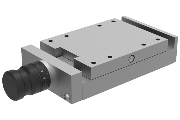
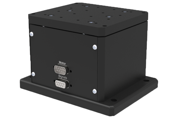
Front drive micrometer positioning stages
X Stage
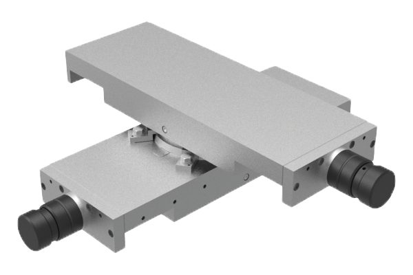
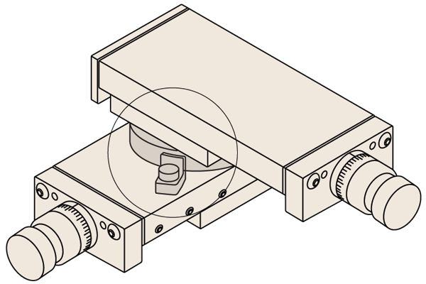
XY Stage
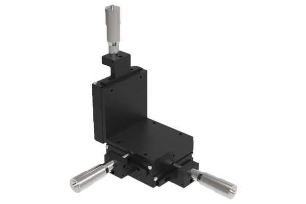
XYZ Stage
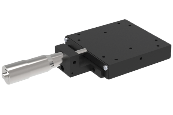
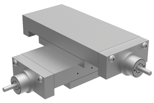
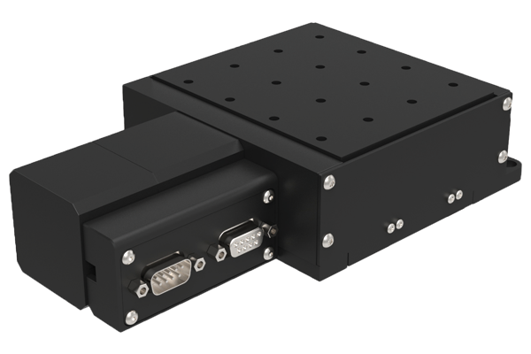
Side drive micrometer positioning stages
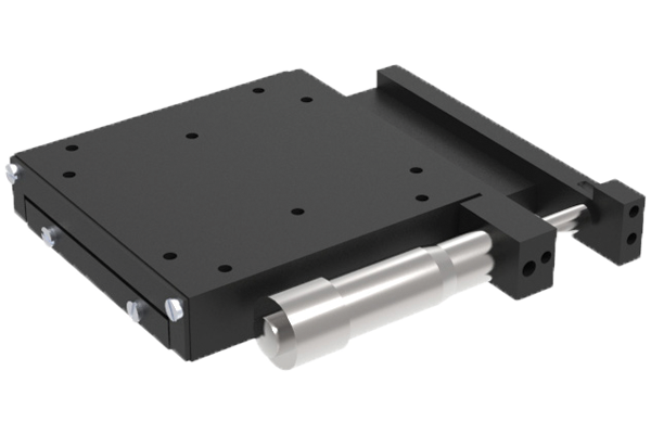
X Stage
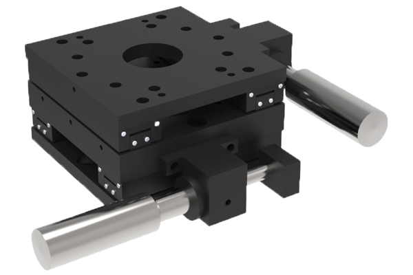
XY Stage
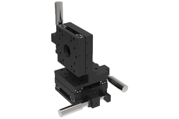
XYZ Stage
Technical Specs
Limit and position switches:
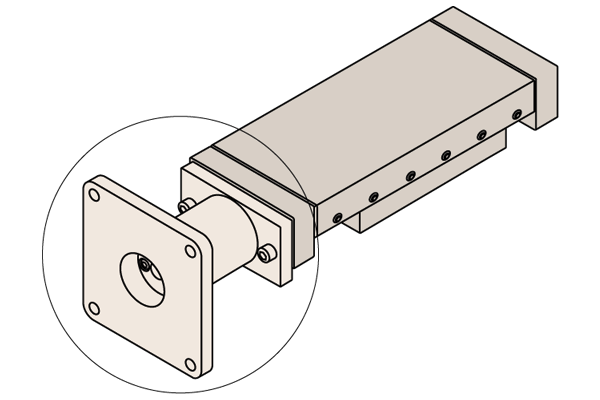
End of Travel and/or Home Position switches can be installed onto these linear stages – please see the drawings of the brackets that attach to the stages that result from this requirement.
The End of Travel switch kit comes with two switches mounted to the base at each end – there are two flags mounted to the carriage. These flags are adjustable for either the full range of travel or a limit amounted. The Home Position switch comes with one flag mounted to the base in the centre – with an adjustable flag mounted to the carriage, allowing the home position to be set at any point.
The switches are photoelectric sensors that operate on a supply voltage of 5 to 24V DC. The repeatability is 5 microns, the response time is 100 microseconds. The sensors are available in both NPN and PNP outputs. Quick fitting hook up cable (3 metres) provided.
| Part no. | Order no. | Ls1 | Ls2 |
L3141 Lead screw driven stage - Size 1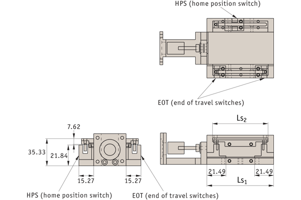 | L3141.025L3141.050L3141.075L3141.110 | 50,876.2101,6152,4 | 38,163,588,9139,7 |
| Part no. | Order no. | Ls1 | Ls2 |
L3142 Lead screw driven stage - Size 2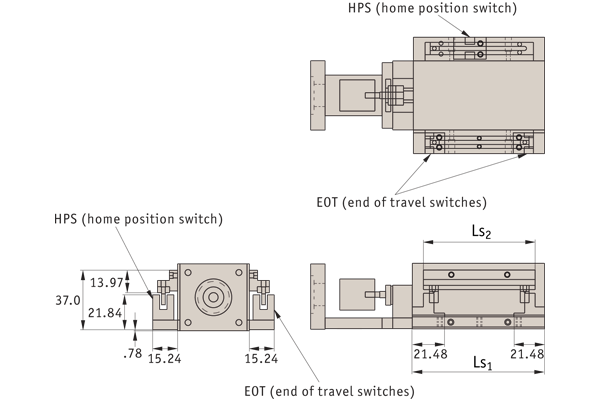 | L3142.025L3142.038L3142.050L3142.075L3142.100 | 57,276,288,9108,0152,4 | 41,360,373,092,1136,5 |
| Part no. | Order no. | Ls1 | Ls2 |
L3143 Lead screw driven stage - Size 3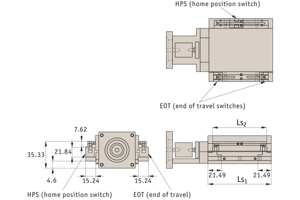 | L3143.025L3143.050L3143.075L3143.100L3143.150L3143.200L3143.250L3143.300 | 76,2101,6127,0152,4228,6279,4330,2381,0 | 60,385,7111,1136,5212,7262,5314,3365,1 |
Heavy duty linear stages
Plain stages
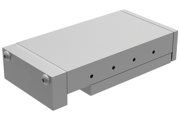
Lead screw & handle
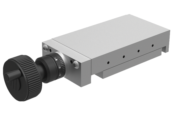
Lead screw & knob
XY0 stage
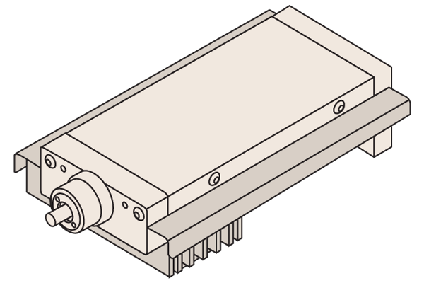
Motorised stage
XY stage
Available with the following sliding elements:
Cross roller: For medium loads, low friction.
Dovetail: Less expensive, higher friction, higher loads.
Needle roller: Highest loads, low friction, more expensive.
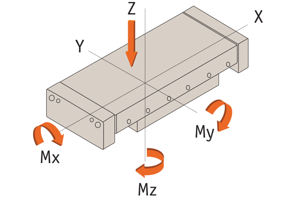
Moment loads
All loads shown in tables are based upon an evenly distributed load with slide in centre position. All loads apply to a single slide.
| Crossed roller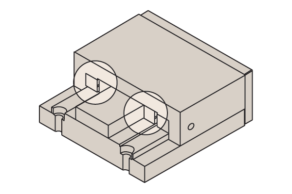 | Dovetail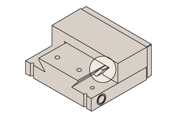 | Needle roller |
| Width | 30-300mm | 30-400mm | 100-400mm |
| Stroke | 12-950mm | 10-600mm | 50-800mm |
| Load capacity | 29 kN | 33 kN | 59 kN |
| Max speed | 20 m/min | 15 m/min | 20 m/min |
| Coefficient of friction | 0,003 | 0,1 | 0,003 |
| Straightness of travel (μ)
| Stroke up to | Slide type | Slide length up to | Parallelism (μ)
| ||||
| 50 | Cross roller & Needle roller | 100 |
| ||||
| 100 | Cross roller & Needle roller | 200 |
| ||||
| 200 | Cross roller & Needle roller | 300 |
| ||||
| 300 | Cross roller & Needle roller | 400 |
| ||||
| 400 | Cross roller & Needle roller | 600 |
| ||||
| 500 | Cross roller & Needle roller | 800 |
| ||||
| 600 | Cross roller & Needle roller | 1000 |
| ||||
| 700 | Cross roller & Needle roller | 1210 |
| ||||
| 800 | Cross roller & Needle roller | ||||||
| 50 | Dovetail | 100 |
| ||||
| 100 | Dovetail | 200 |
| ||||
| 200 | Dovetail | 300 |
| ||||
| 300 | Dovetail | 400 |
| ||||
| 400 | Dovetail | 600 |
| ||||
| 500 | Dovetail | 800 |
| ||||
| 600 | Dovetail | 1000 |
| ||||
| 600 | Dovetail | 1210 |
|
Height tolerance for roller and dovetail slides
± 0,01mm. DIN 7168 medium is the dimensional variations of the sliders. Closer tolerances upon request.
Rectangularity of XY-tables
± 0,005mm per 100mm slide length
Carriage - Standard holes
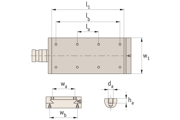
Base - Standard holes

Carriage
| w1 | l1 | la | lb | ha | da | wa |
| 50 | 76 | 36 | - | 4 | 4xM4 | 24 |
| 50 | 102 | 62 | - | 4 | 4xM4 | 24 |
| 50 | 152 | 112 | - | 4 | 4xM4 | 24 |
| 75 | 102 | 62 | - | 5 | 4xM5 | 34 |
| 75 | 127 | 87 | - | 5 | 4xM5 | 34 |
| 75 | 152 | 112 | - | 5 | 4xM5 | 34 |
| 100 | 152 | 112 | - | 6 | 4xM6 | 52 |
| 100 | 203 | 163 | - | 6 | 4xM6 | 52 |
| 100 | 254 | 214 | - | 6 | 4xM6 | 52 |
| 100 | 305 | 90 | 265 | 6 | 4xM6 | 52 |
| 150 | 203 | 163 | - | 6 | 8xM8 | 95 |
| 150 | 305 | 90 | 265 | 6 | 8xM8 | 95 |
| 150 | 406 | 240 | 366 | 6 | 8xM8 | 95 |
| 150 | 406 | 240 | 366 | 6 | 8xM8 | 95 |
| 200 | 457 | 240 | 417 | 8 | 8xM10 | 120 |
| 200 | 610 | 190 | 570 | 8 | 8xM10 | 120 |
| 300 | 410 | 190 | 370 | 15 | 8xM10 | 200 |
| 300 | 610 | 190 | 570 | 15 | 8xM12 | 200 |
| 300 | 710 | 290 | 670 | 15 | 8xM12 | 200 |
| 300 | 910 | 290 | 870 | 15 | 8xM12 | 200 |
| 300 | 1010 | 490 | 970 | 15 | 8xM12 | 200 |
| 300 | 1210 | 490 | 1170 | 15 | 8xM12 | 200 |
Base
| l2 | lc | ld | wb | da | ha |
| 50 | 20 | - | 37 | 4xM4 | 4 |
| 76 | 36 | - | 37 | 4xM4 | 4 |
| 101 | 61 | - | 37 | 4xM4 | 4 |
| 76 | 36 | - | 56 | 4xM5 | 5 |
| 101 | 61 | - | 56 | 4xM5 | 5 |
| 101 | 61 | - | 56 | 4xM5 | 5 |
| 126 | 86 | - | 74 | 4xM6 | 8 |
| 126 | 112 | - | 74 | 4xM6 | 8 |
| 152 | 163 | - | 74 | 4xM6 | 8 |
| 203 | 188 | - | 74 | 4xM6 | 8 |
| 228 | 112 | - | 120 | 4xM8 | 12 |
| 152 | 163 | - | 120 | 4xM8 | 12 |
| 304 | 90 | 264 | 120 | 4xM8 | 12 |
| 253 | 213 | - | 120 | 4xM8 | 12 |
| 304 | 90 | 264 | 155 | 8xM10 | 8 |
| 406 | 190 | 366 | 155 | 8xM10 | 8 |
| 308 | 90 | 268 | 255 | 8xM10 | 15 |
| 408 | 190 | 368 | 255 | 8xM12 | 15 |
| 408 | 190 | 368 | 255 | 8xM12 | 15 |
| 508 | 290 | 468 | 255 | 8xM12 | 15 |
| 508 | 290 | 468 | 255 | 8xM12 | 15 |
| 608 | 190 | 568 | 255 | 8xM12 | 15 |
Locking device
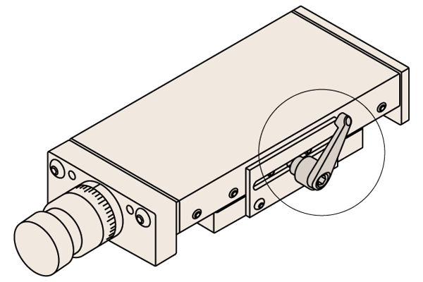
Either mounted on a side plate, a swivel rod or direct to slideway - dependent on stage type.
Bellows
Recommended for general industrial applications. The installation of bellows aff ects the stroke, height and width of the slide. The bellows are made of PVC and can be used at temperatures up to 80° consult us for dimensions.
Swivelling plates
These can be rotated 360° in graduations of 10°. Graduations of 10° up to 90° clockwise and counterclockwise.
Motor adaptors
For slides with a width greater than 75mm, a flanged motor adaptor with coupling can be provided. Please advise motor size.
Mounting brackets
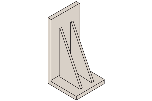
From cast iron or on request aluminium.
Product Selection
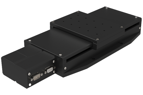
L3500
Medium duty motorised stage
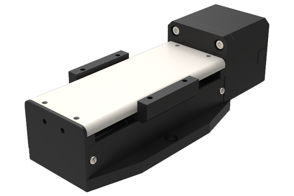
L3504
Heavy-duty motorised stage
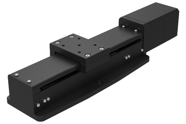
L3505
Motorised linear stage
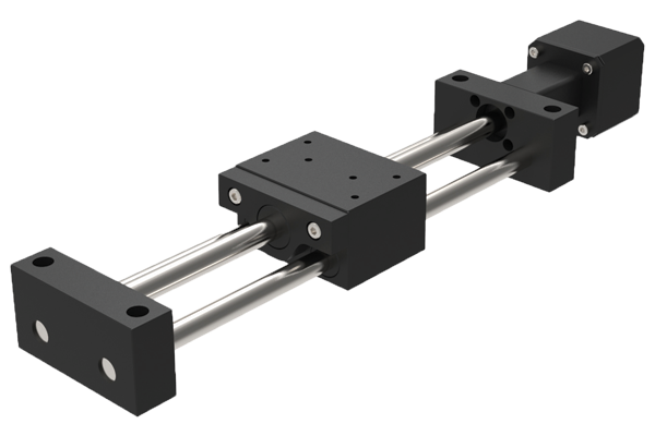
L3506
Miniature motorised stage
L3508
Motorised linear stage
L3510
Motorised linear stage
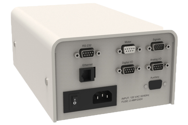
L3521
Single axis stepper controller
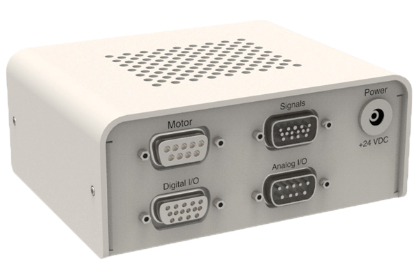
L3522
Two axes stepper controller
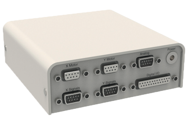
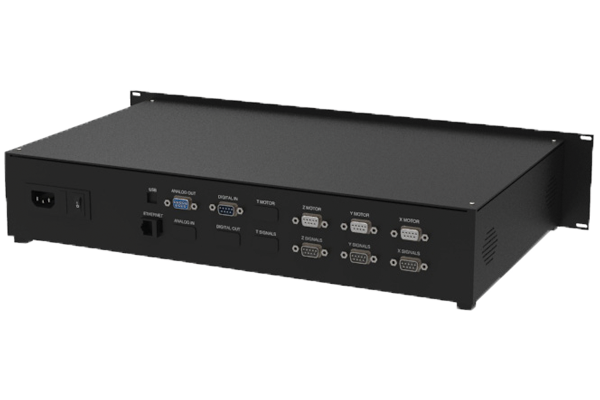
L3524
Multi-axes stepper controller
L3525
Single axis servo controller
L3550
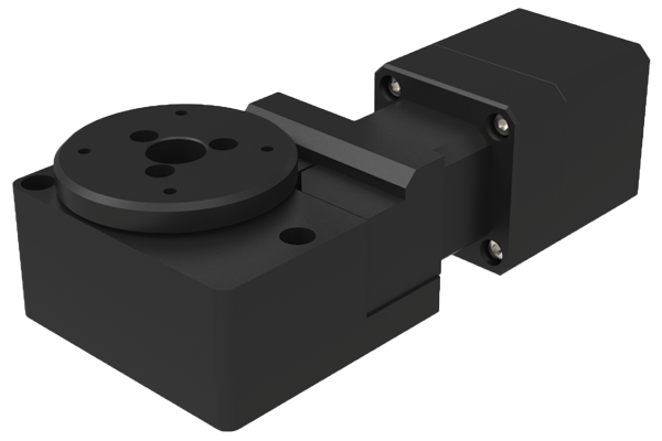
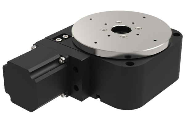
Motorised rotary stage Ø50
L3552
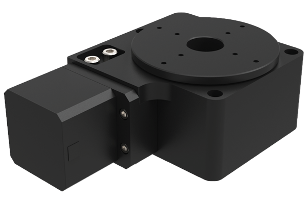
Motorised rotary stage Ø75
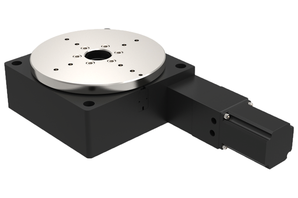
L3554
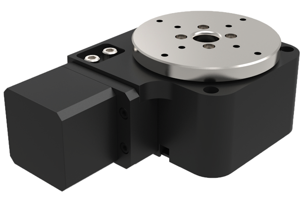
Motorised rotary stage Ø75
L3556
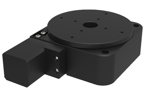
Motorised rotary stage Ø125
L3558
Motorised rotary stage Ø125
L3559
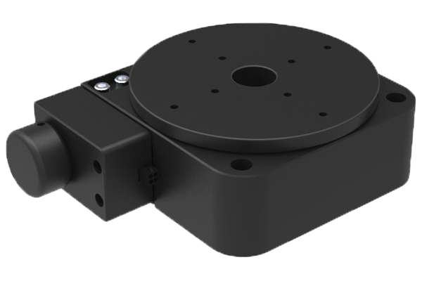
Manual rotary stage Ø125
L3562
Motorised rotary stage Ø200
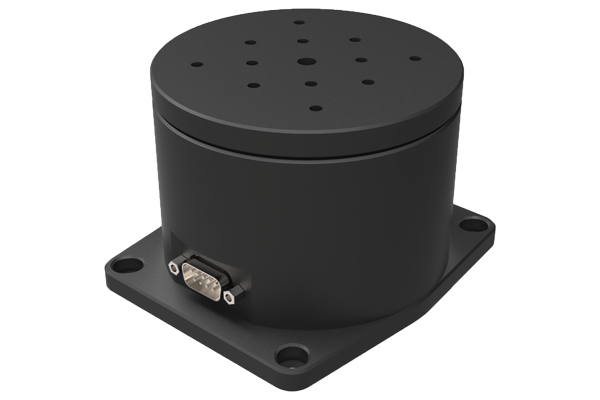
L3569
High speed rotary table
L3591
Vertical lift stage motorised
L3592
Vertical lift stage motorised
L3550 Ø50 Rotary stage
- Motorised.
- Accurate to 70 arc-secs, repeatedly to 3 arc/sec.
- Loads up to 4.5kg.
L3552 Ø75 Rotary stage
- Motorised.
- Accurate to 70 arc-secs, repeatedly to 5 arc-secs.
- Loads up to 11kg.
L3554 Ø75 Rotary stage, heavy duty
- Heavy duty.
- Motorised.
- Accurate to 70 arc-secs, repeatedly to 3 arc-secs.
- Loads up to 20kg.
L3556 Ø125 Rotary stage, medium duty
- Motorised.
- Accurate to 70 arc-secs, repeatedly to 5 arc-secs.
- Loads up to 25kg.
L3558 Ø125 Rotary stage, heavy duty
- Heavy duty.
- Motorised.
- Accurate to 70 arc-secs, repeatedly to 3 arc-secs.
- Loads up to 45kg.
L3662 Ø200 Rotary stage
- Motorised.
- Accurate to 70 arc-secs, repeatedly to 5 arc-secs.
- Loads up to 125kg.
| Part no. | Stepper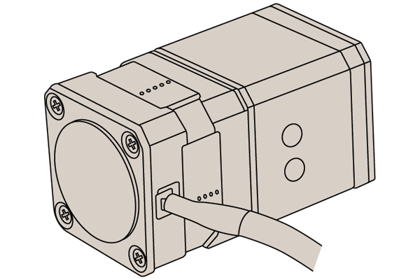 | MDrive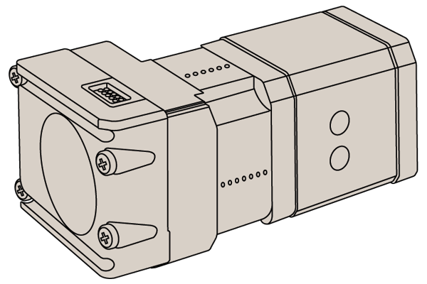 | Servo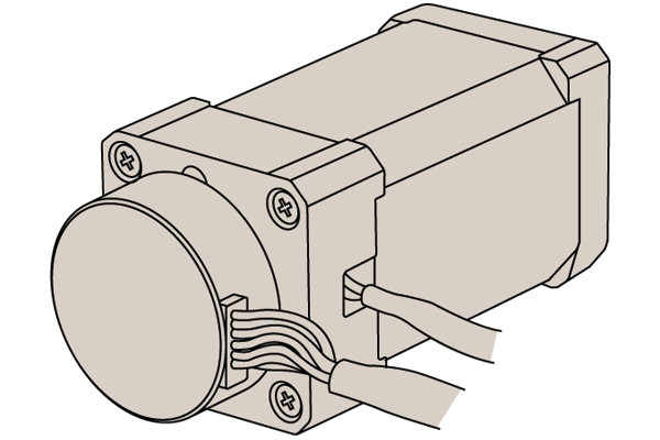 |
| L3550 | ✔ | ✔ | ✖ |
| L3552 | ✔ | ✔ | ✖ |
| L3554 | ✔ | ✔ | ✔ |
| L3556 | ✔ | ✔ | ✖ |
| L3558 | ✔ | ✔ | ✖ |
| L3562 | ✔ | ✔ | ✔ |
General Guidance
Motorised Stages
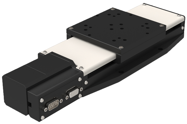
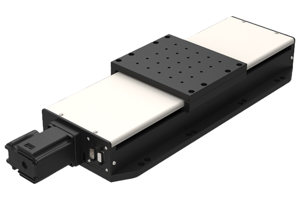
Our motorised linear stages are precise, heavy duty and available from 25mm stroke to 800mm.
They can be easily controlled either with an Intelligent motor (this is a motor with an inbuilt driver and controller) or with a motor and one of our motion controller stages.
Programming for both the intelligent motor (less expensive) and the motion controllers is very simple and we provide free software and sample source code for Labview, VB, C++, OSX etc. It is also possible to download a stand-alone programmed to the device so it can run independently of a host.
We also offer a Joystick controller.
The stages can be readily supplied in X, XY, XZ and XYZ configurations and can also be used with our range of rotary tables (L3550 to L3562).
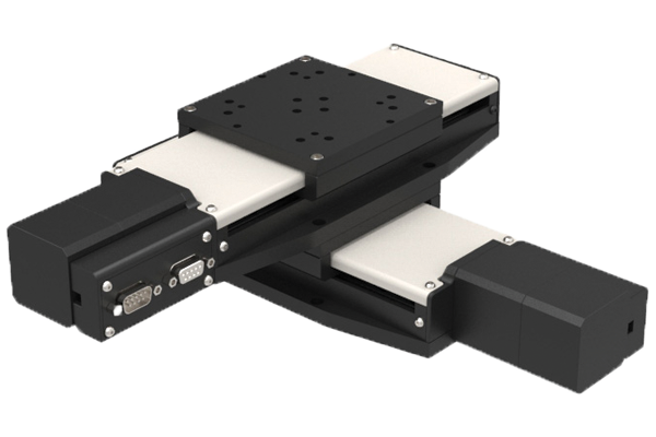
XY Assembly
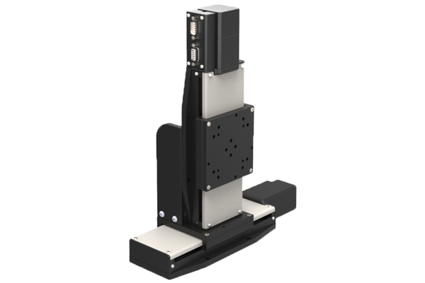
XY Assembly
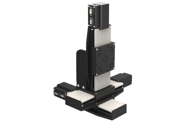
XY Assembly
Using intelligent motors
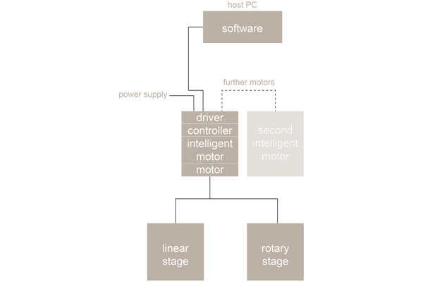
- RS-485 - USB connection.
- Can run independently from host.
- Joystick control option
Using motion controllers
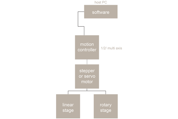
- RS-485 - USB connection.
- Can run independently from host.
- Joystick control option
Stepper limitations
For all of their advantages, stepper motors have a number of limitations which can cause significant implementation and operational issues depending on your application. Stepper motors do not have any reserve power. In fact, stepper motors lose a signifi cant amount of their torque as they approach their maximum driver speed. A loss of 80% of the rated torque at 90% of the maximum speed is typical.
Stepper motors are also not as good as servo motors in accelerating a load. Attempting to accelerate a load too fast where the stepper cannot generate enough torque to move to the next step before the next drive pulse will result in a skipped step and a loss in position. If positional accuracy is essential, either the load on the motor must never exceed its torque or the stepper must be combined with a position encoder to ensure positional accuracy.
Stepper motors may also suffer from vibration and resonance problems. At certain speeds, partially depending on the load dynamics, they may resonate and be unable to drive the load. This may result in skipped steps, stalled motors, excessive vibration and noise.
Servo limitations
Servo motors are capable of delivering more power than stepper motors, but do require much more complex drive circuitry and positional feedback for accurate positioning. Servo motors are also much considerably expensive than stepper motors and are often harder to find. Servo motors often require gear boxes, especially for lower speed operation.
The requirement for a gearbox and a position encoder makes servo motor designs more mechanically complex and increases the maintenance requirements for the system. To top it all off , servo motors are more expensive than stepper motors before adding on the cost of a position encoder.
Summary
Selecting the best motor for your application depends on a few key design criteria for your system including cost, positional accuracy requirements, torque requirements, drive power availability, and acceleration requirements. Overall, servo motors are best for high speed, high torque applications while stepper motors are better suited for lower acceleration, high holding torque applications as well as generally being less expensive and easier to control.
Stepper Motor
- Standard
- With rotary encoder (1000 line)
Intelligent stepper motor
- Standard
- With rotary encoder (512 line)
Servo motor
- Standard
- With rotary encoder (1000 line)
Intelligent stepper motor
- No need for separate motion controller.
- Inbuit motor, driver and controller.
Options
- Standard
- With rotary encoder (512 line)
Separate motor controllers (single axis)
Single axis stepper controller
Single axis servo controller
Intelligent stepper motor
- Standard
- With rotary encoder (512 line)
Stepper motor
- Standard
- With rotary encoder (1000 line)
Servo motor
- Standard
- With rotary encoder (1000 line)
Controllers
L3294 Single axis stepper motor controller
- Communicate via RS-232 or Ethernet interface
- Uses virtually any programming language
L3295 Two axis stepper motor controller
- Communicate via RS-232 or Ethernet interface
- Programming via Labupu, VB, C++ and OSX etc.
- Stand alone programs can be downloaded
- Max output of 1.5A
L3296 Multi axis stepper motor controller
- Communicate via RS-232 or Ethernet interface
- Can control 4 axis and perform coordinated or independent motion of each or all the axis simultaneously
- Uses virtually and programming language
L3297 Single axis servo motor controller
- Communicate via RS-232 or Ethernet interface
- Uses virtually any programming language
Accessories
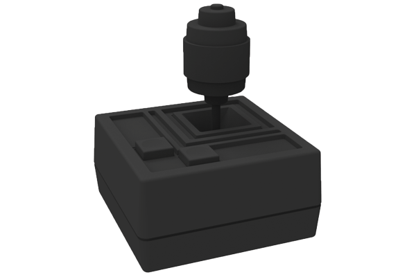
Joysticks
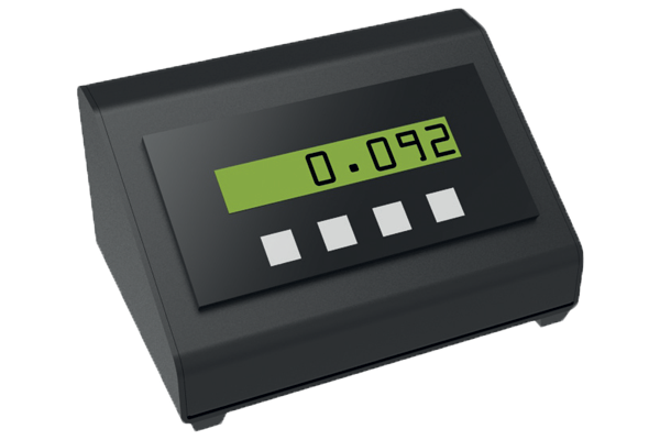
Digital readout
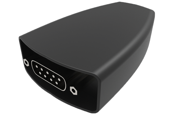
Connector RS232-USB
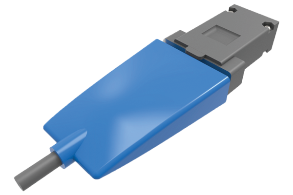
Connector RS422-USB
These have major benefits as they combine the motor (from size NEMA17 up) with an inbuilt driver and controller.
- Stepper or servo motor versions.
- Simple to install
- CE certified
- Free software programming
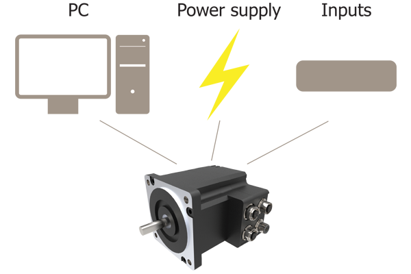
Plug and play
- Download free software
- Connect motor to computer (USB port)
- Connect power supply to the motor
- Start controlling/programming
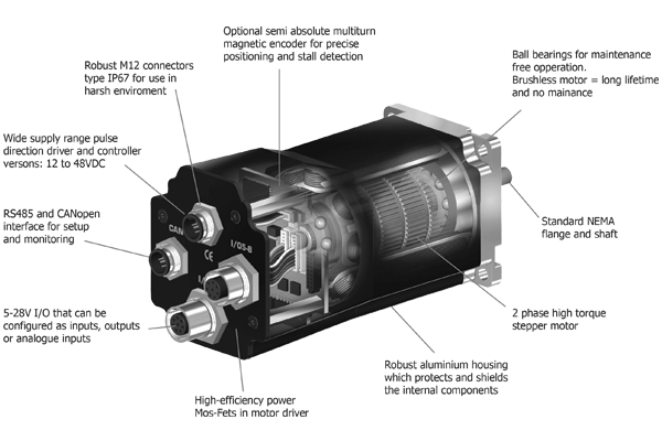
- Low cost solution.
- The I/O points can be set by users to input, output or analogue input.
- NEMA17, 23, 34, 43 and larger sizes available.
- 12-48VDC.
- High torque stepper motors (1.2 to 10.5 Nm).
- Simple Windows software program provided free).
- Also Labview VB etc. programs.
- IP67, Motor brake.
- Optional Joysticks.

Introduction
The software is the main interface for setting up the motor for a specific application. The program offers the following features:
- Choice of the operating mode of the motor
- Changing main parameters such as speed, motor current, zero search type, etc.
- Monitoring the actual motor parameters in real time, such as supply voltage, input status, etc.
- Changing protection limits such as position limits.
- Saving all current parameters to disc.
- Restoring all parameters from disc.
- Saving all parameters permanently in the motor.
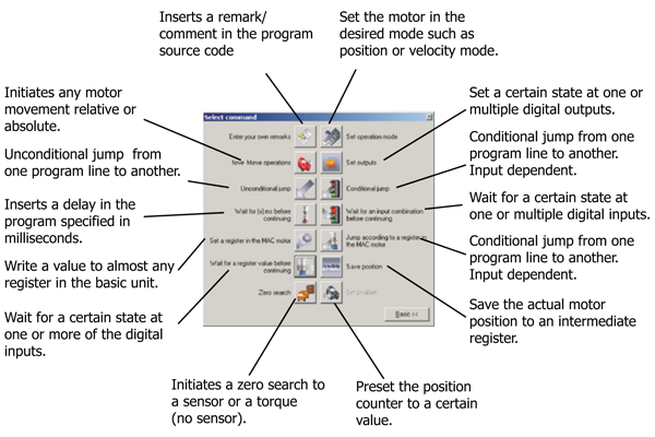
Command toolbox description
The toolbox used for the programming covers 14 different command types. The idea for the commands is to have an easy access to the most common functions in the motor. Some functions seem to be “missing” at first sight but the button “Set register in the quickstep motor” or “Wait for a register value before continuing” gives direct access to 50 function registers. In total this gives a very powerful programming tool since >95% of a typical program can be built using the simple command icons and the last part is obtained by accessing the basic motor registers directly if required.
Factors affecting stage selection
- Size and weight of load (including any moment loads)
- Accuracy (positioning, repeatability and resolution)
- Speed of rotation required
- Means of control
| Parameters | High precision |
| Table diameters (mm) | 50-200 |
| Maximum loads (Kg)HorizontalVertical | 125125 |
| Maximum speed o/secStepper motorServo motor | 25-50180-360 |
| Accuracy (arc-secs)PositioningRepeatabilityResolution | 70"5"<0,7" |
| Control options | Stepper, servo or intelligent motor Motion controllers available |
Factors affecting stage performance
Run-out
The displacement of a measure sensor placed on the surface of the rotary table.
Applied loads
These cause small deformations in the stage bearings and are dependent on the stiffness of the stage, the bearings and the stability and flatness of the mounting surface.
Hysteresis errors
The difference between the control and instructed position.
Backlash errors
Errors caused by the reversal of the direction of travel affected by clearance in the drive chain.
Encoder errors
Imperfections in the operations of the encoder (if present).